Hello everyone. In the last issue, we discussed the complexity of corrosion and how one could determine if spray package corrosion will or will not occur. I listed the nine known factors that cause or contribute to spray package corrosion.
The empirical equation for these nine factors help determine what type(s) of corrosion occurs and how fast corrosion occurs.
Equation 3 provides an empirical equation for all nine factors that could be used to estimate corrosion rates and help determine what type(s) of corrosion are occurring.

The symbols in Equation 3:
• Ψ and Γ have the same meanings as in Equation 2
• Subscript and superscript items have the same meanings as in Equation 2
• ß is proportionality constant that converts the probabilities into corrosion rates
• f (letter or phrase) is the exponent for each group of factors—each is a complex function

Obviously, Equation 3 is more complex than Equation 2. The increased complexity occurs because it answers both the What type(s)? and How fast? questions. Equation 2 only answers the question, Will it corrode?
There are ~362,880 possible combinations of the nine factors that could cause corrosion or contribute to spray package corrosion—making corrosion probabilistic instead of deterministic. Groups that have probabilities (ψ1-9) >1 affect corrosion and those that are (ψ1-9) = 1 have no effect on corrosion. Consequently, Equation 3 provides information about the type(s) of corrosion that occur.
Let’s look at each group in Equation 3, proceeding from left to right for the first two (pH and metal type), and then from the second line (surface tension) to the bottom.
The first group estimates how pH affects the corrosion rate magnitude. ψ1 is the probability that the pH of formula water or contaminant water will decrease or increase the corrosion rate, and the exponent “a” determines how much pH affects the rate, and is typically a single number.
The second group (metal type) estimates how the type of package interacts with the product. Spray package metals could be tinplated steel, tin-free steel, aluminum and aluminum foils. Coated metals, laminated metals and uncoated metals corrode at different rates when exposed to the same formula. Consequently, the second factor accounts for how different types of metals/coated-metals influence the rate of spray package corrosion. The exponent f(h) is a complex function that generates a single number for each metal type exposed to a specific formula.
The third group estimates how surface tension affects package corrosion. Surface tension determines how easy or difficult it is for formula ingredients to:
1. Absorb onto uncoated metal surfaces;
2. Diffuse through polymer coatings and laminate films; and
3. Adsorb onto substrate metals under laminated films and coatings.
The exponent f(i) is a complex function that generates a single number for each component surface tension.
The fourth group estimates how electrochemically active (ECA) ions and molecules affect corrosion rates. The ECAϒj symbol represents the electrochemical activity for individual ions and molecules in a formula that are electrochemically active. The exponent f(j) is a complex function that generates a single number for each specific electrochemically active ion or molecule in a formula.
The fifth group estimates how the metal surface treatments affect corrosion rates. Surface treatments include polymer coatings or laminate films, tin coatings on steel and chromium/chromium oxide coatings on steel (tin-free steel). The exponent is a complex function that generates a single number for each type of surface treatment.
The sixth group estimates the cathode/anode area ratios on the metal surface that determines if pitting corrosion will occur and how fast pitting corrosion will penetrate through a package. Metal surfaces—both coated and uncoated—are composed of cathodic areas where valence electrons are transferred from surface atoms to ECA formula ingredients and anodic areas where the atoms are ejected from the bulk metal as ions.
This factor also helps determine if corrosion will be either general or localized. Pitting corrosion occurs when the exponent f(m) is >0. The exponent is a complex function whose magnitude is determined by the specific chemical composition of a formula and the type of package materials.
The seventh group accounts for emulsion stability. Emulsions break after a certain age and when exposed to either high or low temperatures. Water and cream phases are typically generated when an emulsion breaks—and one or more of these phases could be very corrosive. Consequently, the exponent for this factor is an equation that is a function of both temperature and emulsion age. This particular factor is zero for non-emulsion products and greater than one for emulsions.
The eighth group is the age of a product in its spray package. General corrosion typically occurs shortly after a package is filled; pitting corrosion follows afterward. The exponent “n” for this factor is typically a single number that is determined by the specific chemical composition of a formula and the type of package materials.
The ninth factor accounts for formulas incorporating corrosion inhibitors. There is no such thing as a one-size-fits-all corrosion inhibitor.
There are also many types of formula ingredients, such as fragrances, that in some instances act as corrosion inhibitors. Consequently, the exponent of this factor is a complex function that accounts for specific formula chemical compositions, pH, synergy between all formula ingredients that could inhibit corrosion and the effective concentration range for each ingredient that inhibits corrosion.
To summarize both Parts 1 and 2 of this series:
• Predicting corrosion with Equation 2—the theoretical equation for whether corrosion will or will not occur—does not provide operational data for making decisions on product-package longevity.
• There is no available public domain knowledge for the parameters needed to use empirical Equation 2 and Equation 3 for predicting corrosion and corrosion rates.
Consequently, corrosion testing with either a storage stability test and/or an electrochemical corrosion test are the only ways to reliably measure and predict if corrosion will occur and how fast corrosion will penetrate spray packaging.
Both types of tests must be conducted with the appropriate testing procedures (e.g., a minimum of one year for a storage test), data analysis procedures and models for predicting both service lifetimes and their associated percent failures.
Thanks for your interest and I’ll see you in an upcoming issue. Contact me at 608-831-2076; rustdr@pairodocspro.com or from our two websites: pairodocspro.com and aristartec.com. SPRAY
Hello everyone. Corrosion is a probabilistic process, not a simple deterministic process with only one causative factor. There are approximately nine major factors that could cause corrosion, which means there are 362,880 possible combinations of these factors that could cause spray package corrosion. This is why corrosion is probabilistic.
There are three basic corrosion questions that should be addressed with each new or derivative formula in order to provide operational information about package-formula compatibility and avoid very costly corrosion failure:
1. Will a formula or a derivative formula corrode the chosen spray package?
2. What type of corrosion will occur?
3. How fast will corrosion penetrate the package materials?
In other words, what is the package service lifetime with your formulas?
In this month’s column, we’re going to use math to illustrate why corrosion is so complex and often (seemingly) unpredictable. I’ll use aerosol container corrosion as the example since aerosols are among the most widely used packages for consumer packaged goods (CPG).
Figure 1 and Figure 2 illustrate the multiple types of corrosion that often occur inside aerosol containers and on aerosol valves. In addition, the types of corrosion noted in Figure 1 can be general corrosion and/or pitting corrosion. This means there are 14 possible types of corrosion in steel aerosol containers, 10 possible types of corrosion in aluminum aerosol containers and six types of corrosion on aerosol valves.

The percentages to the right of the steel aerosol container in Figure 1 show how often corrosion was observed in ~7,500 steel aerosol containers used for a variety of CPG products. Similar percentages are expected for aluminum aerosol containers and aerosol valves. Simultaneous occurrence of several different types of corrosion inside a spray package is common, hence the percentages in Figure 1 add up to over 100%.
Can corrosion be modeled mathematically?
The Gibbs free energy equation in Equation 1 indicates that corrosion can be modeled mathematically:
Equation 1
∆G = nFK (corrosion potential)
Where:
• ∆G represents theoretical Gibbs free energy
• n is the number of electrons in the corrosion reaction
• F is a conversion factor known as the Faraday constant
Metal corrosion occurs when ∆G is a negative number.
There are published lists with corrosion potentials for specific metals and environments, but no lists for aerosol containers with a CPG. In addition, corrosion potentials are also probabilistic and the function of at least five factors for aerosol containers:
1. Formula water or contaminant water pH
2. The type of package (e.g., aerosol, laminated foil bag, etc.)
3. The formula-package surface tension
4. Electrochemically Active (ECA) ions and molecules in a formula
5. The internal package metal’s surface treatment, such as coated and uncoated
Hence, we need an empirical equation for the corrosion potential in Equation 1. Equation 2 provides such an equation, written in the Gibbs free energy format.
These five factors are enclosed inside the Equation 2 brackets and the various symbols mean:
• ψ is the probability for each factor group. ψ ranges from 0–1 and has no effect on corrosion when it = 0 (and removed from the calculation). The greatest effect is when ψ is 1
• Γ indicates that a group has multiple sub-factors (from 1 to a number symbolized by a letter) that multiply together.
Notice there is also a probability associated with this type of group that allows for the magnitude of the affect by each group to be nothing 0–1.
• ϒj is the chemical activity coefficient for each ECA in a formula, such as water
• F is the Faraday constant, a conversion factor for electro-chemical corrosion
• K is the proportionality constant for the overall equation
• Concentrations are indicted by square brackets, such as [ECA]
• Exponents for each factor are the super-script lower-case letters

Most of the factors in Equation 2 are unknown.
Figure 1 shows that there are multiple corrosion types that can occur inside spray packages. Consequently, Equation 2 only determines that corrosion is possible and does not answer the other two basic questions:
The last two questions could be addressed with a single equation. However, this equation is much more complex than Equation 2.
Currently there are nine known factors that influence the magnitude of spray package corrosion rates and the corrosion type(s) that occur:
1.Water pH
2.Type of package metal
3. Surface tension
4. Chemical activity for each ECA ion and molecule in a formula
5. Package metal surface treatment
6. The cathode to anode area ratio
7. Emulsion stability
8. Package age (time)
9. Corrosion inhibitors (both added and ingredients that unexpectedly act as inhibitors)
These nine factors are all part of Equation 3, which will be discussed in the next issue.
Thanks for your interest and I’ll see you in September. Contact me at 608-831-2076; rustdr@pairodocspro.com or from our two websites: pairodocspro.com and aristartec.com. SPRAY
Hello everyone. In previous editions of Corrosion Corner, I’ve discussed the cost of in-market corrosion failures. These are package corrosion failures that occur with an existing or derivative commercial product.
In this issue’s column, I’m going to refine the prior discussions on in-market failures and add in-development failures from package corrosion observed during new/derivative product development.
The parameters for calculating failure-costs are summarized in Table 1.

These types of failures have costs that include internal budget costs, out-of-pocket costs, and loss of revenue when a fraction of a firm’s consumers/customers switch to a competitor’s brand when a failure occurs.
The numbers in Table 1 are from discussions with multiple attorneys, our current research on package-failure cost and experience. The actual numbers for each company could be different from those used here.
Table 2 lists the typical number of full-time employees (FTE) on a team investigating both in-development and in-market package failures. The last row of Table 2 summarizes all the yearly FTE costs for in-development and in-market failures.

These examples of calculations for both types of failure costs assume:
• Annual expected sales of $15 million
• A one-year manufacturing delay
• A 20% brand-loyalty revenue loss for five years for an in-market failure with personal injury litigation
• A 50% brand-loyalty revenue loss for five years for in-market failure with wrongful death litigation
Let’s begin with in-development failures caused by package corrosion that occurs during development of a new or a derivative product.
Solving In-development failures for new and derivative products typically involve the FTE personnel listed in the first three rows of Table 2. In-development failure costs are typically resolved within 1–2 years; manufacturing begins shortly thereafter. The costs for 1–2 years are:
• $15,573,948 for a 1-year resolution
• $31,147,896 for a 2-year resolution
In-market failures of commercial products are significantly more costly than in-development failures. Indeed, during my more than five decades of corrosion research and experience, I’ve witnessed examples where a single in-market failure negated decades of profits for a given brand.
In-market failures are more complex, involve more people and have escalating costs as the consequences of the failure become more severe, such as litigation, product recall and revenue loss from reduced brand loyalty.
Table 3 summarizes several scenarios for in-market failure costs that are resolved after one year, using the same assumptions as those for the in-development cost examples. Each row in Table 3 provides a different failure-cost scenario with the estimated cost for each scenario in the last column of each row.
Table 3 illustrates that, as the consequences of a failure become more severe, the costs increase significantly from only paused manufacturing to scenarios involving an in-pantry recall, lost brand-loyalty revenue and litigation. Indeed, a failure resulting in only lost revenue from a manufacturing pause ($15,940,637) is significantly less expensive than a failure where revenue is lost from all consequences of the most expensive litigation ($183,440,637).

How do you minimize the probability of financial losses from in-development and in-market failures? A comprehensive, corrosion control program is needed to minimize the occurrence of both in-development and in-market failures.
A corrosion control program includes corrosion testing and is typically inside a company’s R&D program. The costs of an internal corrosion control program with 2–4 FTE would range from approximately $573,948 to $1,147,896 per year.
Thus, the cost for a corrosion control program is significantly less than the costs for both in-development failures and in-market failures, particularly when an in-market failure involves product recall, litigation and loss of brand loyalty!
Therefore, why doesn’t/wouldn’t your company have a comprehensive internal corrosion control program?
Thanks for your interest and I’ll see you in August. Contact me at 608-831-2076; rustdr@pairodocspro.com or from our two websites: aristartec.com and pairodocspro.com. SPRAY
Hello, everyone. Which chemical most often contributes to or causes spray package material corrosion? Water! Water can be in a formula, either as an ingredient or as a contaminant. There are four reasons why I am so quick to implicate water as the most frequent contributor to or cause of spray package corrosion.
First: Water and metals are thermodynamically unstable when in contact with each other. The simple chemical equations for corrosion of the steel and aluminum used in spray packages by water are:
These two equations show that iron (steel) and aluminum corrosion by water is possible, but do not tell us the corrosion reaction rates of aluminum and iron with water. Corrosion rates are important because they are directly proportional to the spray package service lifetime. Thus, corrosion reaction rates should be measured.
Second: A variety of corrosive ions and molecules dissolve in water. Consequently, water is also a carrier that delivers corrosive ions and molecules to spray package metals and metal foils.
Third: Water easily diffuses through materials, such as polymer coatings and laminate polymer films. Water diffusion degrades and disables coatings and film barrier properties, causing them to lose the ability to protect the underlying metal from corrosion. Water diffusion through polymer coatings/films brings corrosive water, molecules and ions to the metal under the polymer coating/film.
Fourth: Metals and metal-polymer interfaces have a molecular cloud of negative electrons on the surface and at the interface, respectively. Thus, water molecules are drawn to uncoated metal surfaces, and through polymer coatings and films, to these negative clouds. Water molecules cause corrosion when they adsorb onto metals and subsequently remove electrons from the water atoms:

What about anhydrous formulas?
It is extremely difficult to keep anhydrous formulas from being contaminated by small amounts of water. Thus, anhydrous formulas are not immune to corrosion by water.
Water is corrosive as a liquid and a cluster of only 90 water molecules is needed to form liquid water that initiates corrosion (based on thermodynamic calculations). Of course, additional water is needed to sustain corrosion after it initiates. The amount of additional water needed depends on the treatment of the metal or metal-foil surface (such as uncoated or coated/type of coating/etc.) plus the chemical composition of the formula inside the spray package.
Consequently, corrosion testing is needed to determine if an anhydrous formula is corrosive and what is the safe concentration of contaminant water. Corrosion testing can be either an electrochemical corrosion test with the appropriate measurement parameters or a minimum one-year constant temperature storage-stability test.
Please note that raising the storage temperature does not accelerate corrosion of spray package materials, such as aluminum, steel, polymer coatings and films. In other words, raising storage temperature does not shorten the length of the test.
Controlling & preventing corrosion
Spray package corrosion by both formula water and contaminant water can be controlled or prevented. For anhydrous formulas, there often is a non-corrosive concentration range for contaminant water. In other words, corrosion of anhydrous formulas might be controlled or prevented by keeping the concentration of contaminant water inside the non-corrosive range.
Corrosion by formula water can often be prevented with corrosion inhibitors. Indeed, in my almost five decades of corrosion research, testing and consulting, I’ve not found a corrosive formula that could not be inhibited! In some instances, slowing down the corrosion is required; in other instances, corrosion prevention is needed.
A corrosion inhibitor is often only effective for a very specific environment or formula. There are literally thousands of chemicals that might inhibit corrosion, hence finding the most effective corrosion inhibitor often takes time.
Ironically, corrosion inhibitors can actually cause corrosion when their concentration is above or below the effective concentration range. Hence, the effective corrosion inhibitor concentration range should also be determined when developing an inhibitor for a corrosive formula.
Storage testing can be used to screen potential corrosion inhibitors; however, a storage test requires at least one year to complete. Electrochemical corrosion testing is more precise and the quickest way to screen a large number of potential corrosion inhibitors—assuming the appropriate measurement parameters and data analysis protocols are used.
Changing package materials also can, in some situations, control and prevent corrosion. However, the options for changing package materials are more limited than the options for corrosion inhibitors.
In summary, water contributes to, or causes, spray package corrosive because water is:
• Thermodynamically unstable when in contact with metals
• Electrochemically active and causes corrosion
• Moves (diffuses) easily in solutions towards metal surfaces
• Attracted to charged surfaces—indeed the electrical field on charged surfaces often pull water towards the surface, as well as through polymer coatings and polymer films
• A carrier of corrosive ions and molecules
• Degrades polymers so they are not barriers between a formula and the package metal under the polymer coatings and films
Anhydrous formulas are not immune to corrosion. However, in some instances, there is a non-corrosive concentration range for contaminant water.
Corrosion inhibitors are an effective way to control or prevent spray package corrosion by formula water and anhydrous formulas. However, finding an inhibitor that works for individual formula-package systems takes time and the effective concentration for the inhibitor must also be determined.
Corrosion testing is needed to determine:
• If corrosion will occur
• Where in the package corrosion will occur
• The spay package service life with a specific formula
• The non-corrosive concentration range for contaminant water—if one exists
• An effective corrosion inhibitor and its effective concentration range
Thanks for your interest and I’ll see you in July. Contact me at 608-831-2076; rustdr@pairodocspro.com or from our two websites: pairodocspro.com and aristartec.com. SPRAY
Hello, everyone. In March, we covered defects in polymer and tinplate coatings and their relationship with corrosion. The April column covered defects in laminated film bags, along with those found in traditional steel aerosol containers.
Most of the material defects in spray packages are very small, but can still be seen with the unaided eye. There are also microscopic defects that can lead to package corrosion and subsequent failure (leaking, clogged valves, etc.).
The metals used for aerosol spray containers are not pure metals. Instead, they are alloys that are mixtures of metals, plus non-metals, such as carbon and oxygen.
Metal/non-metal compounds, such as metal oxides or metal carbides, are insoluble in the host metal (i.e. aluminum and steel) and form microscopic precipitate particles. These particles are called inclusions and are dispersed throughout the host metals. Inclusions can be flattened and elongated when the metal is rolled from ingots into the sheets for package fabrication (typically for steel containers) and when the metal is extruded from slugs into a container (typically for aluminum containers).
Figure 1 provides a photomicrograph with examples of inclusions in steel. The arrows show the locations for only a few of the many different defects. The dark spots are inclusions and the thin, dark line is a row of inclusions, referred to as a stringer.

Please keep in mind that inclusions are not impurities. Inclusions are material defects resulting from the alloying of a metal with different elements to obtain physical properties, such as the strength and formability needed to form metals into containers.
Inclusions are sites for pitting corrosion and stress cracking. Stress cracking rarely occurs in spray packages. The chemical composition of a formula determines whether or not pitting corrosion occurs at inclusions.
Metals form regular arrangements of atoms, and these atomic arrangements form bulk formations referred to as crystal planes. Crystal planes are often not perfect, and, in some instances, include fragments of planes imbedded among complete planes. The fragments are referred to as dislocations.
Figure 2 provides an example of multiple dislocations that pile-up when a metal is rolled into a sheet. Figure 2 also shows that dislocations could be sites for the initiation of pitting corrosion.
Steel and aluminum metals and alloys all have dislocations. Indeed, there are approximately one million dislocations per square centimeter of metal surface. The chemical composition of a formula determines whether or not pitting corrosion occurs at dislocations.

Figure 3 provides a scanning electron micrograph of tinplated steel, after the tin coating was removed by mechanical polishing. Several different types of defects are noted in Figure 3:
• Different crystal planes form structures referred to as grains, and different types of grains corrode more rapidly than others
• The chemical composition of the boundary between two different types of grains is typically different from the chemical composition of the grains
• The boundary between different grains is not always metallic—the boundary could be either, metallic (dark shadows between grains) or non-metallic (white lines between grains)
• Non-metallic inclusions are also noted in Figure 3 (white particles inside grains)
• Iron carbide compounds are also present in the steel grains—(darker spots)

All material defects in Figure 3 could cause or contribute to spray package corrosion. Aluminum and steel both typically have more than one of the material defect types shown in Figure 3.
The chemical composition of a formula determines whether or not the material defects in Figure 3 contribute to or cause spray package metal corrosion. Hence, corrosion testing is essential for reducing the risk of costly surprise spray package corrosion.
Thanks for your interest and I’ll see you in June. Contact me at 608-831-2076; rustdr@pairodocspro.com or from our two websites: pairodocspro.com and aristartec.com. SPRAY
Hello, everyone. In the last issue, I began a series on material defects in spray packaging and the relationship between these defects and corrosion.
This month, I’ll discuss the more common material defects found in laminated foil bag packages—bag-on-valve (BOV) packaging—as well as both coated and uncoated steel aerosol containers. The final, Part Three discussion will focus on microscopic material defects.
Laminated aluminum foil bag (BOV) packaging
Aluminum foils are laminated on both sides with one or more polymer films and fabricated into bags with an aerosol valve (referred to as bag-on-valve [BOV] packaging) to be inserted into traditional aerosol containers.
Figure 1 shows an example of a micro-bulge on the internal laminate film for a BOV package. This type of material defect is common with this type of packaging. Multiple attempts to obtain a clear cross-sectioning of this defect type have not been successful. Consequently, the properties of micro-bulges and their most likely causes are unknown.
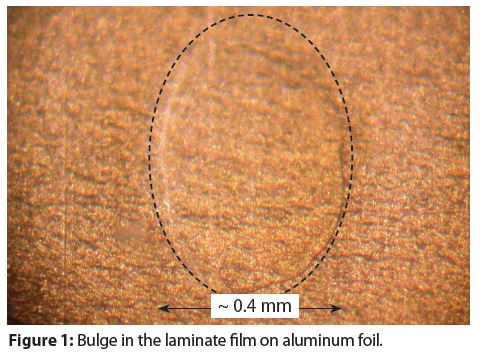
Micro-bulges typically do not contribute to, or cause, laminated aluminum foil bag corrosion. In other words, the probability is not zero, so corrosion tests should be conducted.
Figure 2 provides an example of a polymer film that delaminated at the bag weld. It has been our experience that this type of material defect is rare and can be avoided with optimized welding.
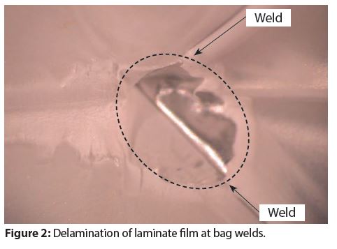
We have not observed instances where this type of material defect contributes to or causes spray package bag corrosion. However, this type of defect could cause metal foil corrosion and bag rupture at the delaminated area.
Figure 3 provides an example of a crack in the aluminum foil under the laminate film. In our experience, this type of material defect is typically random.
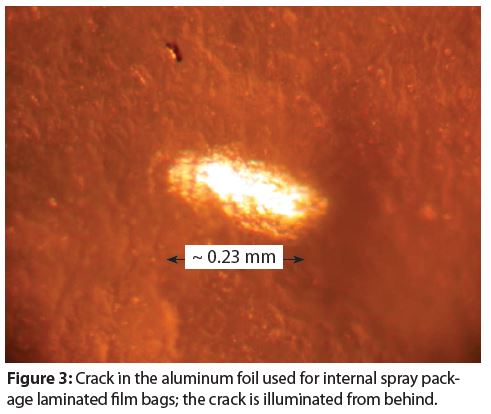
We have not yet observed instances where this type of material defect contributes to or causes laminate foil bag corrosion. However, product that diffuses through the inner laminate layer/layers would also be able to diffuse at the crack through the outer film and cause container perforation and leaking. Consequently, corrosion testing should be conducted.
Tinplated steel aerosol containers
Figure 4 provides an example of an area where the tin coating did not cover (wet) the steel substrate. Non-wetting produces holes in the tin coating that expose either the substrate steel or a very thin, iron-tin alloy layer. Numerous holes in tin coatings, such as that in Figure 4, are present in all tinplated steel aerosol containers.
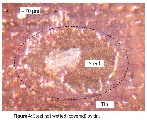
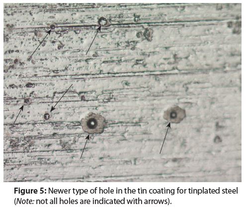
There are two different morphologies for the holes in tin coatings. Figure 4 shows the traditional type of hole morphology and Figure 5 shows a newer type of hole morphology that has appeared within the last three decades.
Notice when comparing Figure 4 and Figure 5 that the newer holes are more symmetrical than the traditional holes. Most likely, the newer hole morphology comes from either a new tinplating bath chemistry composition or a new tinplating process.
Holes in tin coatings are potential sites for pitting corrosion and a formula’s chemical composition determines if pitting corrosion will or will not occur in tin coating holes.
It is unknown if either the traditional hole morphology or the newer hole morphology result in different susceptibilities to, and/or magnitudes of, pitting corrosion. Corrosion testing is the only way to determine if a given formula will cause pitting corrosion at holes in a tin coating.
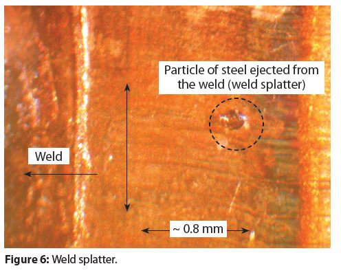
Three-piece steel aerosol container bodies are welded by a diffusion-weld process, using heat and pressure. The heat is produced by an electrical current flowing between the overlapping ends of the tinplated steel sheet used to form the cylindrical container body. In some instances, the combination of pressure and heat is not optimum and a small amount of metal is ejected from under the overlapping ends.
Figure 6 has an example of a small particle of metal ejected from a weld. This phenomenon is referred to as weld spatter. Weld spatter is typically not common. However, pitting corrosion could occur if weld spatter produces a small cavern in the weld and the chemical composition of a formula determines if pitting corrosion will occur in a weld splatter cavern.
This column, and the previous one, both contain examples of macro-defects that can be seen with either the unaided eye or a light microscope. Next month, I’ll complete this series with a discussion of microscopic defects that cannot be seen with the unaided eye and their relationship to spray package corrosion.
Thanks for your interest and I’ll see you in May for Part Three. Contact me at 608-831-2076; rustdr@pairodocspro.com or from our two websites: pairodocspro.com and aristartec.com. SPRAY
Hello, everyone. There is no such thing as defect-free spray package materials. There are always potential concerns as to whether or not defects will contribute to, or cause, spray package corrosion and if corrosion at the point of defect will cause spray packages to fail (leak).
This issue starts a three-part discussion on material defects and their relationship to package corrosion. Material defects in traditional aluminum aerosol containers will be discussed here, and material defects in laminated foil bags in aerosol containers and tinplated steel aerosol containers will be discussed in the next two issues.
Figures 1–6 provide examples of material defects in coated aluminum aerosol containers.
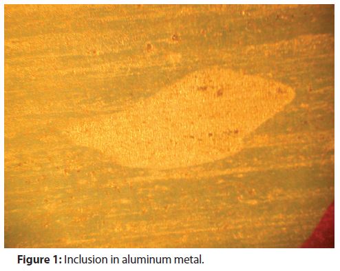
All metal alloys have inclusions in the metal matrix. Inclusions are typically microscopic spherical particles of non-metal components of the aluminum alloy and aluminum/non-metal compounds. Spherical inclusions become distorted and flattened when the metal is formed into a container. Figure 1 has an example of an alloy material inclusion in aluminum aerosol container metal.
I’ve only observed rare instances when inclusions like the one in Figure 1 cause container pitting corrosion. However, corrosion could rapidly perforate containers when corrosion occurs around this type of defect.
Small pieces of metal (divots) are removed from aluminum during the container-forming process. Figure 2 has an example of a divot found in an aluminum aerosol container.
Notice in Figure 2 that the coating backfilled the divot. I have only observed rare instances where this type of metal defect contributes to or causes container corrosion. However, corrosion tests should be used to qualify all new and derivative container-formula systems.
Aluminum aerosol containers are formed with multiple extrusion stages. The containers resemble long tubes open at the top with a bottom during one of the later stages.
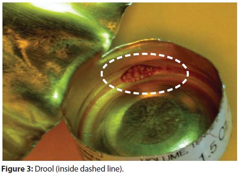
The coating is sprayed inside the open tubes with a nozzle that moves from the bottom of the tube to the top during the coating application. In some instances, coating drips from a nozzle after spraying. Figure 3 has an example of a coating drip in an aluminum aerosol container (referred to as a drool). Corrosion caused by drools is rare, but corrosion testing is still needed.
Entrained air in the bulk coating material sometimes causes a coating nozzle to instantaneously eject the air with a small amount of excess coating. The excess coating on the container surface is referred to as a spit, examples of which are shown in Figure 4. Notice that there are two spits at two different locations inside this example.
Figure 4 also shows variations in coating color. Coating color variations could be caused by variations in the thickness of the coating—a well-known phenomenon in the coatings industry.
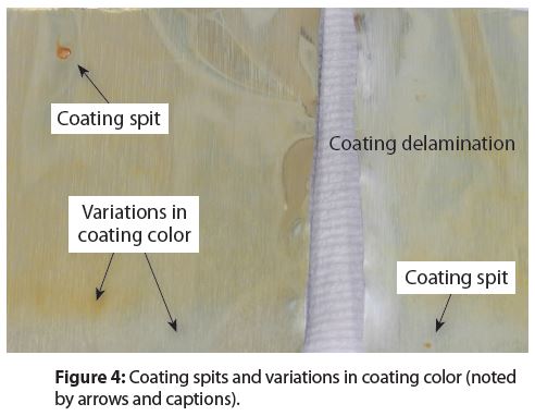
Spits are very common in aluminum aerosol containers. Coating color variations also noted in Figure 4 are caused by coating thickness variations. These variations are also common and I have observed instances where they caused or contributed to random container failures (leaking).
High temperatures are used to cure aerosol container coatings. Coatings and coating components are dissolved in solvents that evaporate during the curing process and small bubbles can form during solvent evaporation. Sometimes these bubbles harden, producing solvent pops like the one in Figure 5.
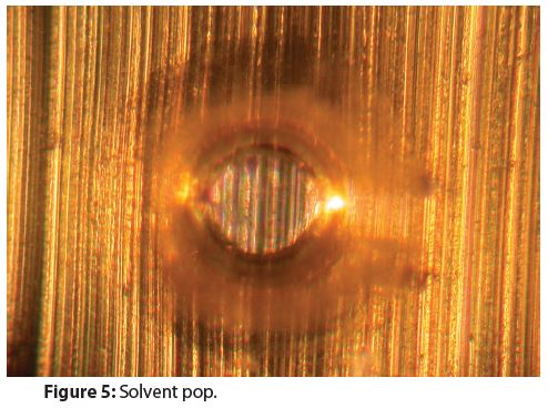
Solvent pops rarely contribute to, or cause, corrosion. However, pitting corrosion inside solvent pops could occur when there is also extensive coating corrosion surrounding a solvent pop.
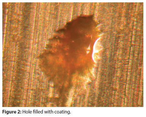
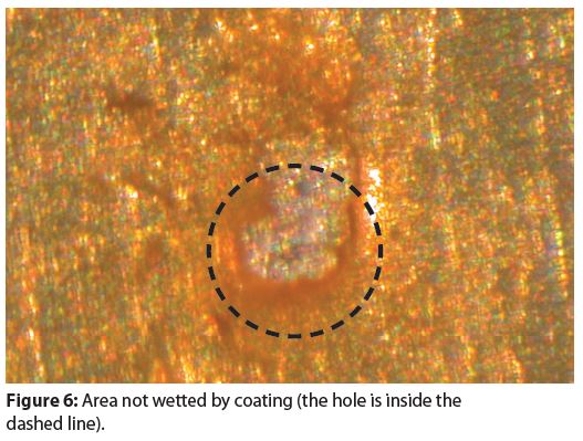
Holes in coatings are very common. Figure 6 has an example of a small area where a coating did not wet (cover) the container metal, resulting in a hole that exposes metal.
This type of defect typically causes pitting corrosion when there is also coating corrosion around the hole.
One or several of the defects shown in Figures 1–6 are present in virtually all aluminum aerosol containers. Consequently, corrosion testing is needed to determine when these defects will contribute to, or cause, container corrosion that leads to failure.
In the next issue, we’ll continue this discussion on material defects in bag-on-valve (BOV) packaging and traditional steel aerosol containers.
Thanks for your interest and I’ll see you in April for Part Two. Contact me at 608-831-2076; rustdr@pairodocspro.com or from our two websites: pairodocspro.com and aristartec.com. SPRAY
Happy New Year, everyone! In the August 2023 edition of Corrosion Corner, I discussed how corrosion failures are very expensive. These occur when packages leak, do not completely exhaust when spraying or when product is discolored or has a malodor because of package corrosion.
The cost of spray package corrosion could include:
• Corrosion testing
• Development of corrosion inhibitors
• Product recall when corrosion unexpectedly causes package or product failures
• Time and resources for investigating package failures
• Commercial or personal injury litigation
• Loss of sales
• Loss of both customer and consumer confidence in the products that failed from corrosion
Precise information on the corrosion costs to our industry is difficult to estimate. The global corrosion cost in 2022 was estimated to be $2.5 trillion, which is approximately 3.4% of the global gross domestic product (GDP) for that year. Clearly, corrosion is a major global concern to all industries, including the aerosol industry.
There are still many gaps in our knowledge about what causes spray package corrosion, as well as how to control and prevent it. These knowledge gaps in spray package corrosion lead to multiple questions that should be considered while developing a new spray product or derivative products for existing product lines.
My original perspective was published in the February 2014 edition of Corrosion Corner. That list still applies to spray packaging corrosion today and has since expanded, so an update is useful. The list of corrosion questions to consider during development of all spray products, changes to a formula’s ingredients, as well as changes in packaging and package materials includes:
1. How does the type of formula water cause or contribute to spray package corrosion?
2. Will an anhydrous formula be contaminated with water at some point in the manufacturing and filling process?
3. Is there a critical contaminant water concentration range for an anhydrous formula, above or below which the formula becomes corrosive?
4. How do the different types of fragrances (e.g., citrus, vanilla, etc.) cause or contribute to the corrosivity of various different types of spray formulas (e.g., aqueous, ethanol-water, emulsions, etc.)?
5. How and when do fragrances behave like corrosion inhibitors?
6. Which fragrance types exhibit the ability to inhibit spray package corrosion?
7. What initiates the various types of spray package corrosion, such as vapor phase, crevice and pitting corrosion?
8. What are the safe formulas—ones that will not cause or contribute to spray package corrosion?
9. Are there specific chemicals to avoid using in specific types of formulas?
10. What causes package corrosion to be random in its type—and its location—inside a package?
11. What are the best practices for spray package corrosion testing?
12. How should corrosion tests be designed to address:
a. Formula composition variability during manufacturing
b. Raw material variability
c. Variability of package materials?
This is quite a list! Reviewing it gives an appreciation for the breadth and depth of factors that influence whether or not spray package corrosion will occur with a given type of package/formula combination.
Hopefully this list also provides guidance on what areas of corrosion research need further development. Obviously, research produces more expedient and effective spray package corrosion control and prevention programs for companies using spray packaging for their products.
Thanks for your interest and I’ll see you in February. Contact me at 608-831-2076; rustdr@pairodocspro.com or from our two websites: pairodocspro.com and aristartec.com. SPRAY
Hello, everyone. This month, we’ll complete the three-part series begun in (part 1, October), (part 2, November) with a discussion on how coating glass transition temperature (Tg) changes when formula ingredients permeate coatings, as well as how higher storage test temperatures can produce misleading corrosion test results.
Coatings have physical properties, such as tensile strength and barrier strength that disappear when the coating temperature is at or above the coating’s Tg. In other words, a coating loses its physical properties when the temperature is above its Tg.
The internal coating for a spray package is dry before it is filled. Examples of dry coating Tg magnitudes are:
• Epoxies and polybutadiene are around 100°C (212°F)
• Nylon 6 is around 47°C (116.6°F)
• Nylon 6,6 is around 79°C (174.2°F)
• Polypropylene is around -10°C (14°F)
• PET has a Tg between 69°C (156.2°F) and 85°C (185°F), depending on the PET grade
Internal package coatings typically become wet shortly after the package is filled with product, because formula ingredients absorb into and diffuse through the coatings. Consequently, the internal dry coating Tg for a new, unfilled package is higher than the Tg for the same coating after the package is filled with product. For example, the Tg for a dry epoxy coating is 100°C (212°F), but the corresponding Tg for the same wet coating is around 50°C (122°F).
It is often assumed that a higher storage temperature will accelerate both the coating’s and the metal’s corrosion rates, thus allowing the time needed for storage stability corrosion tests to be reduced. This assumption is based on the Arrhenius equation that states chemical reaction rates double for every 10°C (50°F) increase in temperature.
However, metals and coatings do not follow the Arrhenius equation because the corrosion rates for both do not satisfy the two conditions for valid application of the Arrhenius equation:
1. The chemical reaction is first order
2. The chemical reaction rate is controlled by its energy of activation
In addition, metal corrosion is not a pure chemical reaction, but a combination of a chemical reaction (metal atoms change state to metal ions) with an electrical charge transfer between the metal and its environment. An environment can be either a formula or the permeate diffusing through a coating to the metal underneath.
Figure 1 illustrates how the Tg for a wet coating changes with increasing temperature. The metal corrosion rate under an epoxy coating is plotted on the Y-axis (log scale) and the corresponding temperature is plotted on the X-axis. The liquid-permeate in this case is water, and the coating was completely saturated.
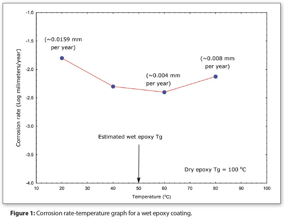
The inflection point for the graph is around 50°C (122°F), which is the most likely estimation for the wet epoxy coating Tg.
The corrosion rate in Figure 1 decreases from approximately 0.016mm per year at 20°C (68°F), to approximately 0.004mm per year at 60°C (140°F) (-1.8 and -2.3, respectively on the Y-axis). In this case, increasing the temperature actually decreases corrosion instead of increasing it, contrary to expectations from the Arrhenius equation.
In addition, the corrosion rate at 20°C (68°F) (0.0159 mm/year) is more than three times larger than the rate at 40°C (104°F) (0.005 mm/year), indicating that corrosion is worse at room temperature (20°C/68°F). This trend also contradicts the Arrhenius equation. I have actually seen numerous storage tests where the room temperature corrosion was worse than the higher temperature corrosion, and vice versa.
It’s tempting to say from Figure 1 that temperature accelerates corrosion as the temperature is increased above 50°C (122°F). However, the corrosion rate at 80°C (176°F) should actually be greater than 0.016mm per year instead of 0.008mm per year–also not consistent with the Arrhenius equation. Consequently, it’s more accurate to conclude that the wet coating is no longer a barrier when temperatures are above the 50°C (122°F) wet epoxy Tg.
Therefore, I typically do not recommend shortening storage test length with higher storage temperatures. Corrosion test length can be reduced with electrochemical measurements when the appropriate instruments, measurement parameters, exposure times, analysis protocols, sample size and data analysis and interpretation protocols are used.
Summary of Parts 1–3
Part 1: Coatings do not always prevent corrosion and are not always needed to prevent corrosion. Whether or not a coating is needed to protect a metal from corrosion is determined by a complex interaction between a formula’s chemical composition, the type of metal and the type of coating, as well as a variety of metal surface attributes that produce various coating defects.
Part 2: Defects in coatings are always present and typically not visible with either the unaided eye or a light microscope. Consequently, electrochemical measurements with sensitive instruments are needed to detect and measure if these defects will or will not cause package corrosion.
Part 3: The Tg of a coating decreases when it becomes wet. Absorption of formula ingredients into coatings cause them to become wet and subsequently degrades coating properties, such as its Tg. Raising storage temperatures to evaluate the corrosion resistance of coated metal packages does not reliably predict package corrosion in a smaller amount of time.
Thanks for your interest and I’ll see you next year. Contact me at 608-831-2076; rustdr@pairodocspro.com or from our two websites: pairodocspro.com and aristartec.com. SPRAY